Creating trace entries
This information describes:
- Creating component trace entries (CTEs) and placing them in trace buffers
- Understanding the fields in a CTE
- Organizing the variable data in a CTE.
Your trace entries can be in any format. However, to be able to use IPCS to display them, use the ITTCTE mapping macro to create CTEs. You can trace a maximum of 60KB of application-unique data in each CTE.
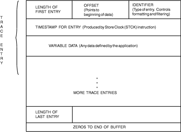
Figure 1 is an example of a CTE
with a trailing length,
which is a length field at the end of the entry.
Figure 1. Component Trace Entry in
a Trace Buffer

Follow this procedure when creating your CTEs
and placing them
in buffers:
- Start the trace buffer with a complete CTE at offset 0.
- Continue adding CTEs without any gaps between the trailing length field (CTELENE) of the previous CTE and the starting length field of the next CTE (CTELENP).
- When the buffer reaches a stage where the entire next CTE cannot fit, IBM® recommends that you clear the remaining portion of the trace buffer to zeros. At this point, you have the choice of either using a new buffer or wrapping and reusing the same buffer. If you are using the external writer, use a new buffer so that component trace can capture your full trace buffer asynchronously while you are writing trace entries to a new buffer. If you do not require trace data to be captured asynchronously, or if you can afford to lose old trace data, you might reuse the same buffer.
Once the application creates all its trace entries, places them in trace buffers in storage, and externalizes them either in a dump or by using the external writer, IPCS can format each entry according to instructions you specify in a CTRACE format table. Use the FMTTAB parameter on CTRACE DEFINE to specify the name of the load module that contains the CTRACE format table. See z/OS MVS IPCS Customization for information about creating a CTRACE format table.