 z/OS DFSMSdfp Utilities
 z/OS DFSMSdfp Utilities
|
Previous topic |
Next topic |
Contents |
Contact z/OS |
Library |
PDF
4248 FCB Module Structure z/OS DFSMSdfp Utilities SC23-6864-00 |
|
|
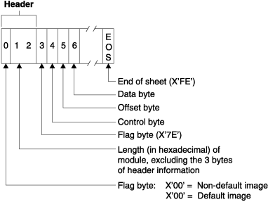
The FCB data following the header information consists of at least five bytes: a flag byte (X'7E'), a control byte (containing information about the horizontal copy feature and printer speed), an offset byte, one or more FCB data bytes (similar to the 3800 data byte for each physical line of the form), and an end-of-sheet byte (X'FE'). The syntax of the 4248 FCB module is shown in Figure 1. Figure 1. 4248 FCB Module Structure
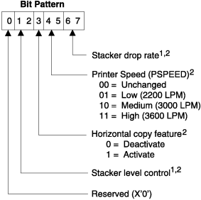
 The control byte is a bit pattern describing whether the horizontal copy feature is active and what printer speed is to be set when the FCB is loaded into the buffer. The structure of the control byte is shown in Figure 2. Figure 2. 4248 FCB Module Control Byte
 Notes to Figure 2
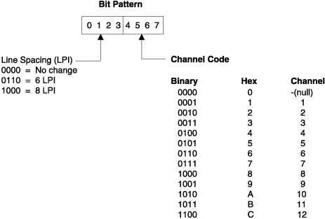
The offset byte follows the control byte and is set either to zero or to the print position of the horizontal copy (2 through 168). The data byte is a bit pattern similar to that produced for the 3800 printing subsystem. Each data byte describes one of 12 channel codes for vertical forms positioning and one of the allowed lines-per-inch codes for vertical line spacing. The structure of the data byte is shown in Figure 3. Figure 3. 4248 FCB Module Data Byte
 The total number of lines defined in the module must be equal to the length of the form. 


|
 Copyright IBM Corporation 1990, 2014 Copyright IBM Corporation 1990, 2014 |