Potential bottlenecks in the data flow for IBM Spectrum Protect operations
In operations such as client backup and storage pool migration, data moves through many physical components that can affect the speed of the operations. Understanding the characteristics of these components can help when you are working to improve performance.
Data flow for client backup operations over a LAN
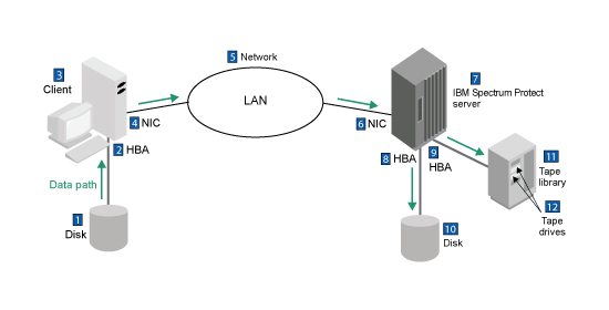
Figure 1 shows data flow in a typical configuration for client backup operations over a local area network (LAN). For a client backup operation, the data flow starts at the client disk (item 1 in the graphic and table) and ends at one of the devices for the server storage pools (item 10 or 12).
The data for backup operations flows through many hardware components, any of which are potential bottlenecks. The following table describes characteristics of the hardware that can affect performance.
| Item in Figure 1 | Item | Key characteristics that can affect performance | Details |
|---|---|---|---|
| 1 | Disk for the client system | Disk type and rotational speed | |
| 2 | Host bus adapter (HBA) that connects the disk to the client system | HBA type and its capabilities | |
| 3 | Client system | The speed of the I/O bus, the number of processors, the speed of the processors, and the amount and speed of RAM | Use of data compression, data deduplication, and encryption, including Secure Sockets Layer (SSL) protocol, can affect processor performance on the client system. If processor usage is too high on the system, consider adding more processors, or turning off the options that enable compression, data deduplication, or encryption. Then, see whether performance improves. For information about tuning for client memory limits, see Reduce client memory use. Software such as firewalls and antivirus programs might affect the efficiency of client operations. For example, during a restore operation, an antivirus program might scan the contents of each restored object, checking for virus signatures. If you suspect that a firewall or antivirus program is slowing client operations, consider temporarily turning the firewall or antivirus program off to see whether performance improves. For tips to minimize the impact of firewall or antivirus programs on other applications, see the documentation for those programs. |
| 4 | Network interface card (NIC) that connects the client system to the LAN | NIC type and its capabilities | A fast network interface card (NIC) improves network throughput. If you cannot use the latest NIC in your configuration, consider adjusting the client TCPWINDOWSIZE option to improve network throughput, particularly on client systems that are geographically distant from the server. Adjust the TCPWINDOWSIZE options in small increments; a window size that is larger than the buffer space on the network interface adapter might actually degrade throughput. For more network considerations, see Tuning network performance. |
| 5 | Network | The many components on a network, and the effective speed of data transfer over the network, which is limited by its slowest component | |
| 6 | NIC that connects the server to the LAN | NIC type and its capabilities | |
| 7 | Server system | The speed of the I/O bus, the number of processors, the speed of the processors, and the amount and speed of RAM | |
| 8 | HBA that connects the server to the disk | HBA type and its capabilities | See Tuning HBA capacity. |
| 9 | HBA that connects the server to the tape library | HBA type and its capabilities | |
| 10 | Disk for the server storage pool | Disk type and rotational speed | |
| 11 | Tape library for the server storage pool | Number of drives and mount point availability for the operation | |
| 12 | Tape drive for the server storage pool | Tape type and sustainable speed |
Data flow for client backup operations over SAN
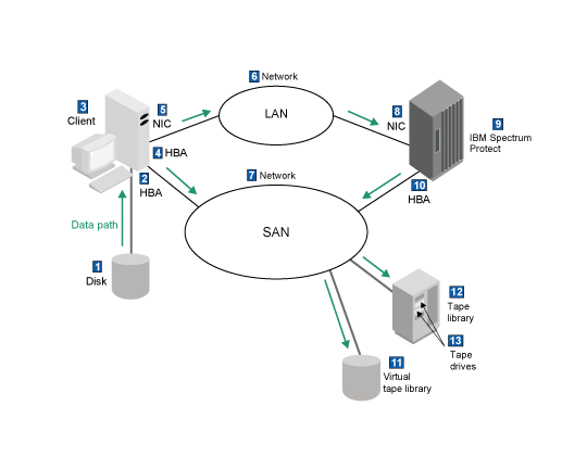
Figure 2 shows data flow in a typical configuration for client backup operations over a storage area network (SAN). Metadata for the backup operation flows over the LAN. For a client backup operation, the data flow starts at the client disk (item 1 in the graphic and table) and ends at one of the devices for the server storage pools (item 11 or 13).
The data for backup operations flows through many hardware components, any of which are potential bottlenecks. The following table describes characteristics of the hardware that can affect performance.
| Item in Figure 2 | Item | Key characteristics that can affect performance | Details |
|---|---|---|---|
| 1 | Disk for the client system | Disk type and rotational speed | |
| 2 | Host bus adapter (HBA) that connects the disk to the client system | HBA type and its capabilities | |
| 3 | Client system | The speed of the I/O bus, the number of processors, the speed of the processors, and the amount and speed of RAM | Use of data compression, data deduplication, and encryption, including Secure Sockets Layer (SSL) protocol, can affect processor performance on the client system. If processor usage is too high on the system, consider adding more processors, or turning off the options that enable compression, data deduplication, or encryption. Then, see whether performance improves. For information about tuning for client memory limits, see Reduce client memory use. Software such as firewalls and antivirus programs might affect the efficiency of client operations. For example, during a restore operation, an antivirus program might scan the contents of each restored object, checking for virus signatures. If you suspect that a firewall or antivirus program is slowing client operations, consider temporarily turning the firewall or antivirus program off to see whether performance improves. For tips to minimize the impact of firewall or antivirus programs on other applications, see the documentation for those programs. |
| 4 | HBA that connects the client system to the SAN | HBA type and its capabilities | |
| 5 | Network interface card (NIC) that connects the client system to the LAN | NIC type and its capabilities | A fast network interface card (NIC) improves network throughput. If you cannot use the latest NIC in your configuration, consider adjusting the client TCPWINDOWSIZE option to improve network throughput, particularly on client systems that are geographically distant from the server. Adjust the TCPWINDOWSIZE options in small increments; a window size that is larger than the buffer space on the network interface adapter might actually degrade throughput. For more network considerations, see Tuning network performance. |
| 6 | Network: LAN | The many components on a network, and the effective speed of data transfer over the network, which is limited by its slowest component | |
| 7 | Network: SAN | The many components on a network, and the effective speed of data transfer over the network, which is limited by its slowest component | |
| 8 | NIC that connects the server to the LAN | NIC type and its capabilities | |
| 9 | Server system | The speed of the I/O bus, the number of processors, the speed of the processors, and the amount and speed of RAM | |
| 10 | HBA that connects the server to the SAN | HBA type and its capabilities | See Tuning HBA capacity. |
| 11 | Virtual tape library (VTL) for the server storage pool | VTL model characteristics that affect the performance of the operation | |
| 12 | Tape library for the server storage pool | Number of drives and mount point availability for the operation | |
| 13 | Tape drive for the server storage pool | Tape type and sustainable speed |
Server storage data flow
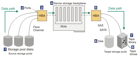
Figure 3 shows data flow in the storage backplane in a server system. The data flow might be for an operation such as migration of storage pool data from disk storage pools to other storage pools. For a migration operation, the data flow starts at the source storage pool (item 1 in the graphic and table) and ends at the device for the target storage pool (item 6 or 8).

The following table describes characteristics of the hardware that can affect performance of the operation.
| Item in Figure 3 | Item | Key characteristics that can affect performance |
|---|---|---|
| 1 | Disks for source storage pools | Disk type and rotational speed |
| 2 | Ports | Multiple connection points to devices |
| 3 | HBA | These devices can have multiple ports. The total amount of data that is being transferred by disks at one time cannot exceed the overall throughput of the HBA. |
| 4 | Server storage backplane | The total of the speeds of all cards that are attached to the backplane cannot exceed the speed of the bus. |
| 5 | HBA | These devices can have multiple ports. The total amount of data that is being transferred by disks at one time cannot exceed the overall throughput of the HBA. |
| 6 | Disks for target storage pools | Disk type and rotational speed |
| 7 | Tape library for target storage pools | Number of drives and mount point availability for the operation |
| 8 | Tape drives for target storage pools | Tape type and sustainable speed |