GDPC infrastructure and GDPC-specific prerequisite conditions
Before setting up a geographically dispersed Db2® pureScale® cluster (GDPC), a number of conditions must be met.
Best practice configuration guidelines
- Three geographically separated sites to communicate with each other through reliable TCP/IP links. Additionally, RDMA (with RoCE or Infiniband) network links or a second private TCP/IP network for member/CF communication can be used on member and CF hosts. The two sites with members and CFs are the production sites, which serve database transactions. The third site acts as a quorum node, it is also known as the tiebreaker host.
- Majority node quorum is used as cluster quorum mechanism in both RSCT peer domain and IBM® Spectrum Scale cluster.
- For the two production sites:
- Should be less than 50 kilometers apart and connected via a WAN or dark fiber with distance
range extenders as required, and with a single IP subnet configured across them. Smaller distances
offer better performance. In extremely light workloads, larger distances, up to 70 or 80 kilometers
may be acceptable. Refer to the following diagram for detail:
Figure 1. Ideal candidates for GDPC 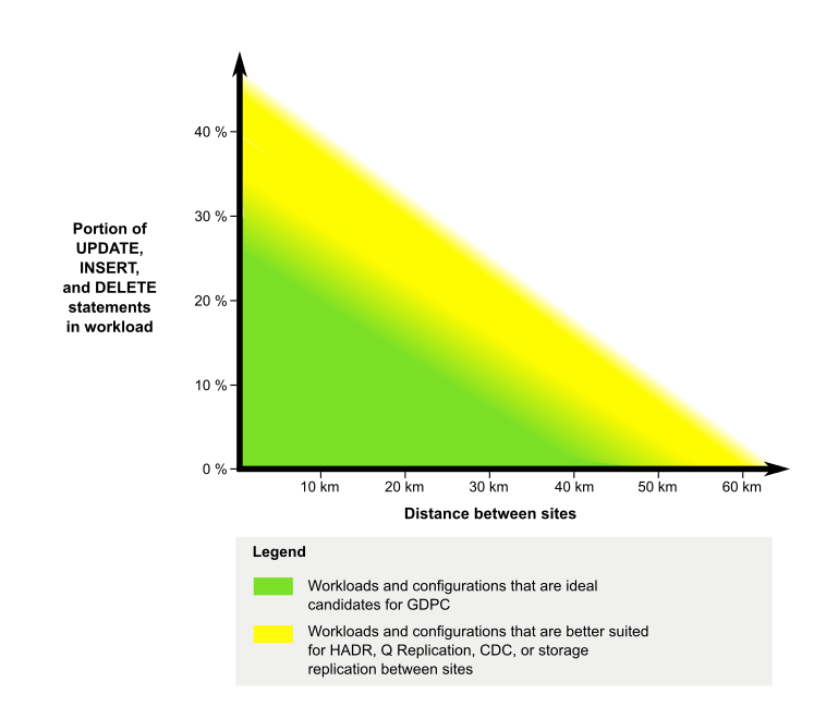
- Each production site has one CF and an equal number of hosts/LPARs and members.
- Each production site has its own dedicated local SAN controller(s). The SAN is zoned such that LUNs used for the Db2 pureScale instance are directly accessible from both production sites. A one-to-one mapping between LUNs is required across sites so each LUN on the first site has a corresponding equally sized LUN on the second site.
- IBM Spectrum Scale synchronous replication is used as the storage replication mechanism.
- If using TCP/IP for member/CF communications:
- Use multiple adapter ports for the member and CF communication for additional bandwidth and redundancy.
- Bond all adapter ports in each member and CF to form a single Ethernet interface. This bonded interface is used for member and CF communication as well as IBM Spectrum Scale heartbeat network.
- Use dual switches in each site for a total of four switches configured in full redundancy fashion.
- If using RoCE for member/CF communications:
- Use multiple adapter ports for the member and CF communication for additional bandwidth and redundancy.
- Use dual switches in each site for a total of four switches configured in full redundancy fashion.
- Setup an additional bonded private Ethernet network interface in each member and CF as the IBM Spectrum Scale heartbeat network.
- If using Infiniband for member/CF communications:
- Only single adapter port per member and CF and a single switch per site is supported. This interface is used for member and CF communication as well as IBM Spectrum Scale heartbeat network.
- Should be less than 50 kilometers apart and connected via a WAN or dark fiber with distance
range extenders as required, and with a single IP subnet configured across them. Smaller distances
offer better performance. In extremely light workloads, larger distances, up to 70 or 80 kilometers
may be acceptable. Refer to the following diagram for detail:
- For the third site:
- A single host (non-member and non-CF) that is dedicated for cluster tiebreaker duty, and is at the same operating system level as other hosts in the cluster
- The IP address associated with the hostname must be on the same IP network as the other hosts in the cluster. This means that all hosts (members, CF, and tiebreaker host) in the same cluster must be able to perform TCP/IP pings among them using their hostname as well as IP address as specified in their respective /etc/hosts file.
- Access to the SAN in the two production sites is not required.
- Assign a single device in /dev to each shared file system in the cluster. No user data is stored on these devices as they are used only to store file system configuration data for recovery purpose and serve as tiebreaker disk for file system disk quorum. (Note: this quorum is at file system level, and not the IBM Spectrum Scale cluster quorum) The size requirement for these devices is minimal. In general, a device between 50 to 100 MB suffices in most cases.
- This device can be a local physical disk or logical volume (LV). Use the following guidelines to
configure the LV:
- Create the logical volumes within the same volume group (VG).
- Assign at least one physical disk to the volume group. The actual number depends on the number of logical volumes required, which in turn, depends on the number of shared file systems. If possible, use two physical volumes for redundancy purposes.
- On platforms where volume group quorum check is supported (such as AIX®) and more than one physical volume is assigned to the volume group, ensure quorum check is disabled.
- Use of the 4-switch configuration on all configurations that support it. Regardless of 2 or 4 switches in the cluster, all switches should be the same model running at the same firmware level.

Support matrix
| Platforms | Minimum OS level | Network type for members and CFs communication | Single or multiple adapter ports supported | Number of switches in main production site |
|---|---|---|---|---|
| AIX |
6.1 TL9 SP5 7.1 TL3 SP5 with IV72952 |
Infiniband (IB) | Single | 1 |
| AIX |
6.1 TL9 SP5 7.1 TL3 SP5 with IV72952 |
10GE RoCE | Multiple | 2 |
| AIX |
6.1 TL9 SP5 7.1 TL3 SP5 with IV72952 |
TCP/IP | Multiple | 2 |
| Red Hat Enterprise Linux (RHEL) | 7.1 | Infiniband (IB) | Single | 1 |
| Red Hat Enterprise Linux (RHEL) | 7.1 | 10GE RoCE | Multiple | 2 |
| Red Hat Enterprise Linux (RHEL) | 7.1 | TCP/IP | Multiple | 2 |
| SuSE Linux Enterprise Server (SLES) | 11 SP2 | Infiniband (IB) | Single | 1 |
| SuSE Linux Enterprise Server (SLES) | 11 SP2 | 10GE RoCE | Multiple | 2 |
| SuSE Linux Enterprise Server (SLES) | 11 SP2 | TCP/IP | Multiple | 2 |
For additional operating system prerequisite details, see installation prerequisites for Db2 pureScale Feature.
For the latest updates to this page, refer to: http://www.ibm.com/support/docview.wss?uid=swg21977337
Switch requirements in a four-switch GDPC configuration
A single-site highly available Db2 pureScale cluster is typically deployed with dual switches connected with multiple physical inter-switch links (ISL) to increase bandwidth and provide redundancy. Link Aggregation Control Protocol (LACP) is setup to prevent the multiple ISLs from forming a network loop between the two switches.
A similar concept is applied to a GDPC with dual switches in each of the two main production sites. In order to provide the same redundancy and additional bandwidth, every switch must be connected to every other switches with multiple physical links in between each pair. The goal is to configure the two switches within the same site to behave a single logical switch. This, in additional to setting up all cross-site links as one logical link, creates a loop-free topology comparable with a single site Db2 pureScale cluster with two switches.
Forming the logical switch in each site and getting the two logical switches to treat each other as a single entity require more than just LACP. Additional protocols and configurations are required on the switch. Some of the mandatory protocols are IEEE standards available on most switch models. Some are proprietary features available only on certain enterprise level switch models and the name of these features vary depending on the vendors. As a result, not all switch models are suitable for four-switch GDPC deployment. Use the following list which describes all mandatory switch features at a high level as a guideline and consult the user manual of the target switch to determine if it is suitable or not.
- Link Aggregation Control Protocol (LACP) - IEEE 802.3ad
Similar to single-site Db2 pureScale cluster, LACP is required to configure the connections between the two switches in the same site as well as switches across the two sites.
- Flow Control - IEEE 802.3x
Similar to single-site Db2 pureScale cluster, flow control (also known as Global Pause) is used to avoid dropped packets when the network congestion occurs. For BNT switch, enable it on all Db2 pureScale related ports except the vLAG ISL ports.
- Same-site virtual trunk supportThe same-site virtual trunk support must provide the following capabilities:
- Pair up the two switches so that it can detect one or all same-site ISL failures.
- If all ISLs fail, one of the switches will force either all ports or at least the cross-sites ISL ports on the other switch to go down. This is usually facilitated by an additional health check connection between the peer switches.
This is not part of IEEE standard and not available on all switches models. Vendors providing this feature include but not limited to the following:- Blade Network Technologies (BNT): Virtual trunk support is referred to as Virtual Link Aggregation Group (vLAG). The same-site virtual trunk is referred to as vLAG ISL.
- Cisco: Virtual trunk support is referred to as Virtual Port Channel (vPC). The same-site virtual trunk is referred to as vPC Peer Links.
- Juniper: Virtual trunk support is referred to as Multichassis Link Aggregation Group (MC-LAG). The same-site virtual trunk is referred to as interchassis link (ICL).
- Peer switch health
check
With same-site virtual trunk, the two switches in the same site work as peers. Depending on the vendor, primary and secondary administrative roles may also be assigned. Regardless of the implementation, the two switches exchange vital health or keepalive information on a frequent basis. Most vendors recommend a separate link to be used for this critical communication. This link must not be part of the virtual trunk. A best practice is to use the switch management ports if available. If the switch management ports are not available, this type of traffic requires a dedicated port and VLAN.
This is not part of IEEE standard and not available on all switches models. Vendors providing this feature include but not limited to the following:- Blade Network Technologies (BNT): this capability is provided by setting up the vLAG ISL health check.
- Cisco: this capability is provided by setting up the vPC Peer-Keepalive Link.
- Juniper: this capability is provided by configuring Inter-Chassis Control Protocol (ICCP).
- Cross-sites virtual trunk support
The switch must provide the capability to aggregate multiple physical connections from more than two switches. In addition, this aggregation should not cause a reduction on available bandwidth. On BNT switches, this capability is provided by aggregating all cross-sites links into a single vLAG.
- Creating IP interfaces on switchAn IP interface typically represents the IP subnet on the network that the switch is on. In Db2 GDPC, IP interfaces are used for two different purposes:
- During initial setup, they can be used as sanity test for connectivity among all hosts and all switches.
- In adapter failure scenario, it serves as the alternative pingable IP address to determine if the host is alive or not.
Site-to-site connectivity
The connection between sites is a key piece of infrastructure in a geographically dispersed Db2 pureScale cluster (GDPC). A Db2 pureScale environment exchanges many messages between members and cluster facilities (CFs). In a GDPC configuration, many such messages traverse the link from one site to the other.
In the case of an InfiniBand high speed interconnect, Longbow InfiniBand extender technology from Obsidian Strategies provides a transparent connection between the two portions of the high speed interconnect network that are located at the two sites, and maintains the ability to execute RDMA operations across a GDPC, even at relatively large distances. Used in pairs at either end of the site-to-site interconnect, the extenders accept a high speed interconnect connection to a site-local high speed interconnect switch, and through it, connect to the members and CF. The extender translates high speed interconnect traffic to and from packets that are sent and received over the site-to-site interconnect (either a ‘dark fiber’ or 10 GB WAN connection).
The extenders themselves add only a very small amount of extra latency to the message protocol. The bulk of the extra site-to-site message latency, when compared to a single-site Db2 pureScale cluster, arises from the simple fact of distance: each kilometer of transmission in glass fiber adds an additional 5 microseconds of delay. So for example, a 10km distance between sites would add (10km x 5 microseconds/km) x 2 for round trip = 100 microseconds of extra latency for most types of messages. In practical terms, workloads that have higher ratios of read activity compared to write activity tend to trigger fewer message exchanges with the CF, and so would be less impacted by additional site-to-site latency.
Current Longbow IB extenders operate at the 4X width Single Data Rate (SDR) or 10 GB data rate between end points (subject to the capacity of the dark fiber / WAN link.) If redundancy or additional cross-site capacity is required, Longbow units can be grouped in multiple pairs between sites (see Figure 1). As well, different Longbow models provide different features which can be useful in certain circumstances, such as encryption in the E-100 and X-100 models, which might be important if the site-to-site interconnect is shared or public and encryption is required by security policies. All current Longbow models are supported with GDPC. Particular configurations, such as the choice of model, use of WAN or fiber, or choice of transceiver wavelength, and other characteristics, are not specified here, and should be selected based on the physical infrastructure to be used, and IT policies in effect. For more information about Longbow IB extenders, contact Obsidian Research. (http://www.obsidianresearch.com/)
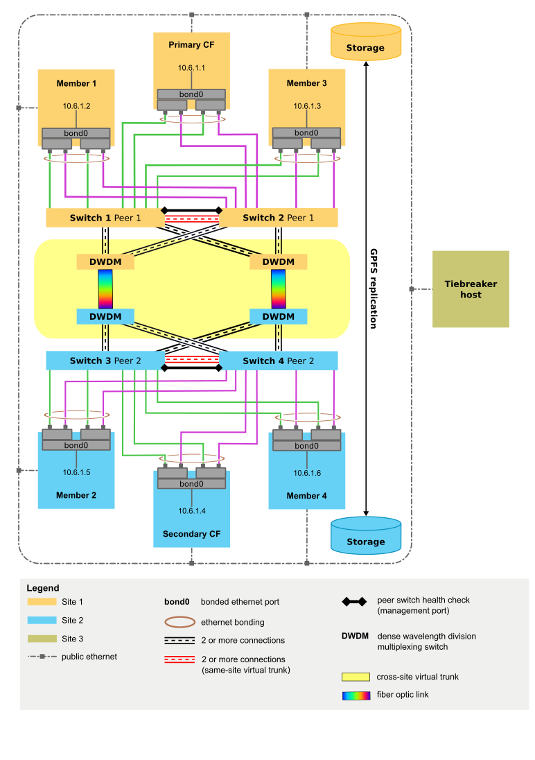
For 10GE RoCE and TCP/IP network, no specialized extender is required. The longe range transmission of data typically leverages existing metropolitan area network infrastructure leased from network wholesalers. Figures 1 and 2 show an example of using dense wavelength division multiplexing (DWDM) transmitters and receivers for long range transmission of data.
Three site configurations
A GDPC is composed of two main sites A and B, with each having an equal number of members and CFs. For example, if site A has two members and one CF, site B must also have two members and one CF. It is a best practice that each main site have the same number of physical machines as well. For example, you do not want to have one machine with four LPARs on one site and two machines with two LPARs each on the other site. One key clustering concept that must be considered is the concept of ‘quorum’. Quorum refers to the number of computer systems that must be online in the cluster in order for the cluster to remain operational. There are two types of quorum, operational quorum and configuration quorum. Operational quorum is needed for software services on the cluster to operate. Configuration quorum is needed to apply configuration changes to a cluster, such as adding a new computer system to the cluster. Configuration quorum requires a strict majority of online computer systems in the cluster, so for example in a cluster that comprises 6 computer systems, at least 4 of those computer systems must be online to perform any cluster configuration updates.
In a non-GDPC environment, operational quorum is typically achieved through the use of a tiebreaker disk. In the event of having only half the computer systems in a cluster online (or a network partition where each half is simultaneously online with no network connectivity to the other half), the disk “tiebreaker” device can be acquired by one half of the cluster. This allows it to achieve operational quorum and run software services (that is, the Db2 pureScale instance) on that winning half of the cluster. In the event of a network partition, the “losing” half would consequently be fenced from the cluster, preventing it from accessing any data on the cluster file systems. The requirement for a disk tiebreaker, however, is that the single tiebreaker disk must be accessible from each computer system in the cluster. In a GDPC environment, this disk must be physically located at one of the two sites, which in the event of a complete network partition between the two sites, would prevent the other site from being able to achieve operational quorum. In the case of clusters with an odd number of nodes, a majority of online nodes is needed for operational quorum. However, in the case where the cluster has an even number of nodes, with an even split of online nodes, a tiebreaker disk decides which subcluster gains operational quorum. In cases where one half of the cluster is down, the online subcluster claims the tiebreaker and gain quorum.
GDPC environments rely on strict majority quorum semantics, where one additional tiebreaker host T is required to maintain quorum in the event of site failure. This tiebreaker host T must be the same architecture type as the machines at the two main sites. For example, it must run the same operating system, although it does not require the same hardware model. A best practice is to also be running the same OS level across all computer systems in the cluster. This additional host does not run any Db2 members or CFs.
A two-site configuration where the tiebreaker host is physically located at one of the two main sites would not be able to achieve either operational or configuration quorum in the event of a site failure at the site containing host T. As such, it is a best practice for continuous availability to use a three-site configuration where the tiebreaker host T is physically located at a separate third site (site C), in order to achieve continuous availability in the event of a failure affecting either of the data processing sites (site A or site B), as majority quorum can be established between site C and the surviving data processing site. In three-site configurations, all three sites can be on different IP subnets as long as each computer system from each site is able to “ping” each other computer system in the cluster. Site C also does not require high speed interconnect connectivity; only sites A and B require high speed interconnect connectivity, with a single high speed interconnect subnet spanning both sites.
To aid in problem determination, it is a best practice to have all computer systems at all sites configure their system clocks to the same timezone.
Firewall Settings
If a network level firewall is setup on each member and CF in the cluster, ensure the relevant ports are opened to allow communications among all pureScale hosts. Refer to Screening router firewalls for TCP/IP ports required by Db2 member and CF processes. Refer to Db2 cluster services port usage information section for TCP/IP ports required by Db2 cluster services.
Zoned SAN storage
GDPC requires that both sites A and B have direct access to each others’ disks. To this end, a number of options are available for extending a SAN across the data centers. Options include transmitting Fibre Channel (FC) traffic directly over ATM or IP networks, or using iSCSI to transmit SCSI commands over IP. Dark fiber is likely to be the fastest but also the most expensive option.
IBM Spectrum Scale synchronous replication
A typical cluster that is not in a GDPC uses IBM Spectrum Scale software in a non-replicated configuration. In such a case, all IBM Spectrum Scale disk activity for a given file system goes to a single IBM Spectrum Scale failure group. When disks are not replicated, a disk failure can leave some of the file system data inaccessible. For a GDPC, however, IBM Spectrum Scale replication is used between sites A & B in order to ensure that an entire copy of the data is available at the surviving site in the event of a total site failure.
GDPC configuration leverages IBM Spectrum Scale replication, by configuring each site to maintain an entire copy of the file system data in its own failure group. As long as quorum is maintained in the cluster, in the event of a site failure (one of the failure groups are lost or inaccessible), the other site can continue with read/write access to the file system.
Tiebreaker host T requires a small disk or partition for each replicated IBM Spectrum Scale file system to be used as a file system quorum disk. The amount of storage for each disk or partition is approximately 50 MB, and these disks or partitions only need to be accessible by host T, and are only used to store filesystem descriptors. I/O activity to disks or partitions that are used to store only filesystem descriptors is very low. Using a full physical volume for this purpose is wasteful and not necessarily practical; configuring a small volume is sufficient for this case. Alternately, logical volumes (LV) can be used as the device type.
Performance impact over single site
The introduction of significant distances between cluster members at different sites increases message latency by an amount of about 5 microseconds per kilometer of glass fiber. In some cases, the amount can be higher, if the connection includes signal repeaters, or is shared with other applications.
Besides distance, the performance overhead experienced by a GDPC configuration also depends on the workloads in use. The greater the portion of write activity (INSERT, UPDATE, DELETE) in the workload, the more messages need to be sent from members to the CFs, and the more disk writes (especially to the transaction logs) need to be made. This increase in disk writes typically leads to higher overhead at a given distance. Conversely, a greater portion of read (SELECT) activity means fewer messages and fewer disk writes, and reduced overhead. As a result, GDPC is best suited for higher read content workload (SELECTs) vs writes (for example 80% or more read activity) with the two sites being 50 kilometers apart or less.
A Db2 pureScale environment is designed to have minimal downtime if a host fails due to hardware or software faults. In the event of a hardware failure, a system must be ‘I/O fenced’ to prevent it from corrupting the data. After a host is I/O fenced, it can no longer access the storage device used by cluster file system in the Db2 pureScale instance, and any I/O attempt is blocked. A key piece of technology to minimize downtime is SCSI-3 Persistent Reserve (PR).
If SCSI-3 PR is not enabled, the IBM Spectrum Scale disk lease expiry mechanism is used to fence failed systems. This typically results in a longer recovery time because of the need to wait for the lease to expire.