Connecting an ESLL or ESLS storage enclosure to your system
To connect an ESLL or ESLS storage enclosure to your system that has support for a serial-attached SCSI (SAS) storage enclosure, complete the steps in this procedure.
About this task
Note: The cables that are used to connect an ESLL or ESLS storage enclosure to a server are different from the cables that
are used with the 5887 disk drive enclosure.
Procedure
-
Confirm the factory-set mode of the enclosure by using information
that is printed on stickers at the rear of the enclosure. Stickers are attached to the lower-left
shelf of the chassis (A) and the center support between the enclosure
services manager modules (B). The stickers indicate whether the enclosure is
set to mode 1, mode 2, or mode 4.
Figure 1. Mode sticker locations at the rear of the ESLL or ESLS storage enclosure 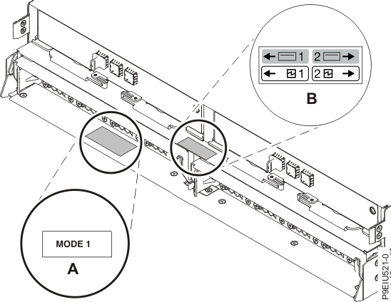
-
Then, complete a mode 1 connection of one enclosure (A) by using a YO12
cable (B) to a single FC EJ0J, FC EJ0K, or FC EJ0M SAS adapter
(C), as shown in Figure 2 and then continue with Connecting cables, power cords, and installing covers.
Note: The single FC EJ0J, FC EJ0K, or FC EJ0M SAS adapter (C) has access to all 12 or 24 drive bays.
Figure 2. Mode 1 connection of one ESLL or ESLS storage enclosure by using a YO12 cable to a single FC EJ0J, FC EJ0K, or FC EJ0M SAS adapter 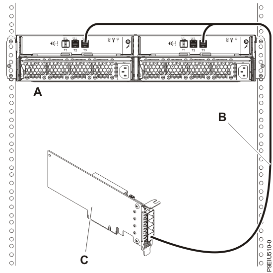
-
Then, complete a mode 1 connection of two enclosures (A and B) by using
YO12 cables (C and D) to a single FC EJ0J, FC EJ0K, or FC EJ0M SAS adapter
(E), as shown in Figure 3, and then continue with Connecting cables, power cords, and installing covers.
Note: The single SAS adapter (E) has access to all 24 or 48 drive bays.
Figure 3. Mode 1 connection of two ESLL or ESLS storage enclosures by using YO12 cables to a single FC EJ0J, FC EJ0K, or FC EJ0M SAS adapter 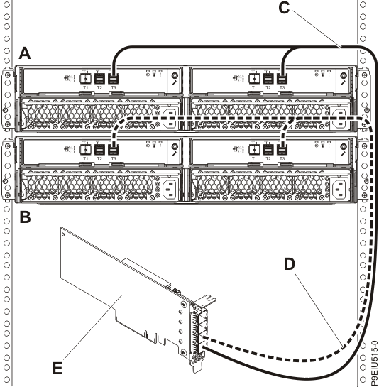
-
Then, complete a mode 1 connection of one enclosure
(A) by using YO12 cables (B) to an FC EJ0L SAS adapter
pair or an FC EJ14 SAS adapter pair (C) with adapter-to-adapter (AA) cables
(D), as shown in Figure 4, and then continue with Connecting cables, power cords, and installing covers.
Notes:
- Each adapter in the SAS adapter pair (C) has access to the other adapter and to all 12 or 24 drive bays.
- For SAS adapter pairs, you must attach the cables to the same port on both adapters.
- Both short legs of the cables must attach to the same side of the enclosure and both long legs of the cable must attach to the other side of the enclosure.
Figure 4. Mode 1 connection of one ESLL or ESLS storage enclosure by using YO12 cables to an FC EJ0L SAS adapter pair or an FC EJ14 SAS adapter pair with AA cables 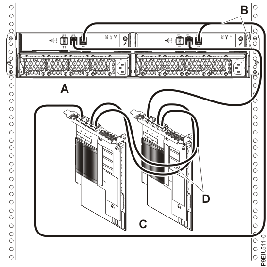
-
Then, complete a mode 1 connection of two enclosures (A and B) by using
YO12 cables (C and D) to an FC EJ0L SAS adapter pair or an FC EJ14 SAS
adapter pair (E) with AA cables (F), as shown in Figure 5 and then continue with Connecting cables, power cords, and installing covers.
Notes:
- Each adapter in the SAS adapter pair (E) has access to the other adapter and to all 24 or 48 drive bays.
- For SAS adapter pairs, you must attach the cables to the same port on both adapters.
- Both short legs of the cables must attach to the same side of the enclosure and both long legs of the cable must attach to the other side of the enclosure.
Figure 5. Mode 1 connection of two ESLL or ESLS storage enclosures by using YO12 cables to an FC EJ0L SAS adapter pair or an FC EJ14 SAS adapter pair with AA cables 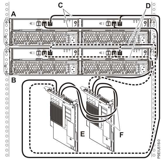
- Then, complete a mode 1 connection of one enclosure
(A) by using two Y012 cables (B) to an FC EJ14 SAS
adapter pair (C) located in PCIe slots C09 and C12 in the 9040-MR9 system
with adapter-to-adapter AA12 cable (D) as shown in Figure 6, and then continue with Connecting cables, power cords, and installing covers. Notes:
- Each adapter in the SAS adapter pair (C) has access to the other adapter and to all 12 or 24 drive bays.
- For SAS adapter pairs, you must attach the cables to the same port on both adapters.
- Both short legs of the cables must attach to the same side of the enclosure and both long legs of the cable must attach to the other side of the enclosure.
- The two bottom ports on the adapters (T0, T1) are dedicated to the cable connections for the internal drive bays.
- This option is only supported with the AIX or Linux operation system.
Figure 6. Mode 1 connection of one ESLL or ESLS storage enclosure by using YO12 cables to an FC EJ14 SAS adapter pair located in PCIe slots C09 and C12 in the 9040-MR9 system with an adapter-to-adapter AA12 cable 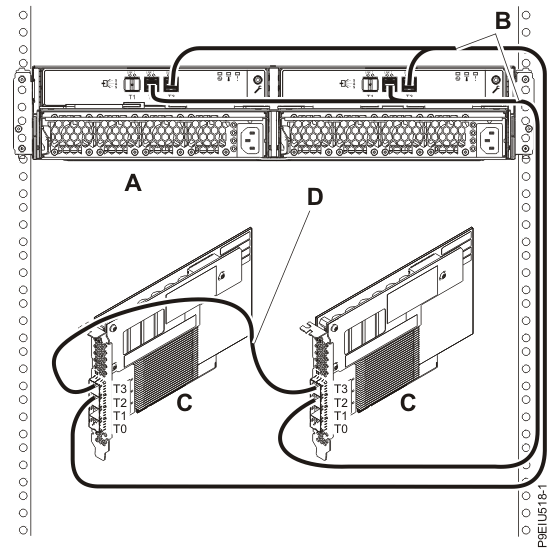
-
Complete a mode 2 connection of one enclosure (A) by using YO12 cables
(B) to two independent FC EJ0J, FC EJ0K, or FC EJ0M SAS adapters
(C and D), as shown in Figure 7. Then, continue with Connecting cables, power cords, and installing covers.
Notes:
- Independent SAS adapter 1 (C) does not have access to the other independent adapter and only has access to drive bays D1 - D12.
- Independent SAS adapter 2 (D) does not have access to the other independent adapter and only has access to drive bays D13 - D24.
Figure 7. Mode 2 connection of one ESLL or ESLS storage enclosure by using YO12 cables to two independent FC EJ0J, FC EJ0K, or FC EJ0M SAS adapters 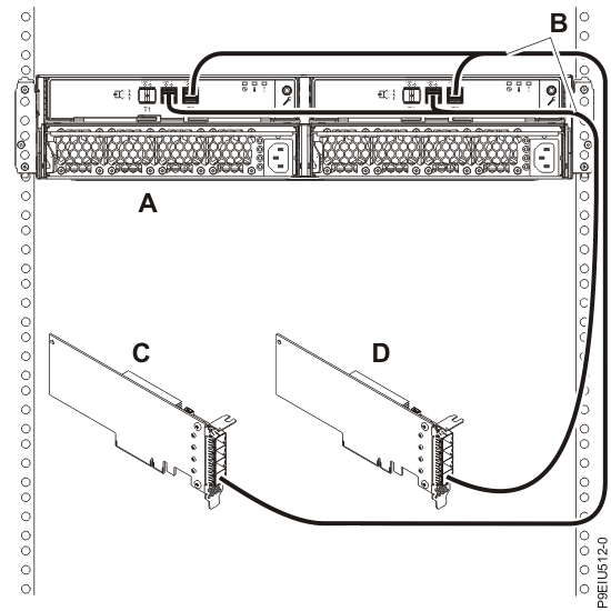
-
Complete a mode 2 connection of one enclosure (A) by using two YO12
cables (B) to an FC EJ0K adapter (C) located in PCIe
slot C12 in the 9040-MR9 system, as shown in Figure 8. Then, continue with Connecting cables, power cords, and installing covers.
Notes:
- The two bottom ports on the adapter (T0, T1) are dedicated to the cable connections for the internal drive bays.
- This option is only supported with the AIX or Linux operation system.
Figure 8. Mode 2 connection of one ESLL or ESLS storage enclosure by using two YO12 cables to an FC EJ0K SAS adapter located in PCIe slot C12 in the 9040-MR9 system 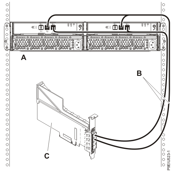
-
Complete a mode 2 connection of one enclosure (A) by using two Y012
cables (B) to two independent FC EJ0K adapters (C)
located in PCIe slots C09 and C12 in the 9040-MR9
system, as shown in Figure 9. Then,
continue with Connecting cables, power cords, and installing covers.
Notes:
- The two bottom ports on the adapter (T0, T1) are dedicated to the cable connections for the internal drive bays.
- This option is only supported with the AIX or Linux operation system.
Figure 9. Mode 2 connection of one ESLL or ESLS storage enclosure by using two YO12 cables to two FC EJ0K SAS adapters located in PCIe slots C09 and C12 in the 9040-MR9 system 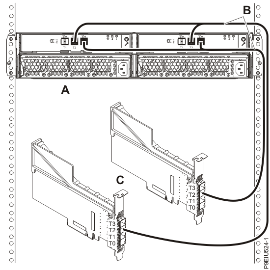
-
Complete a mode 2 connection of two enclosures (A) by using four YO12
cables (B) to two independent FC EJ0K adapters (C)
located in PCIe slots C09 and C12 in the 9040-MR9
system, as shown in Figure 10.
Then, continue with Connecting cables, power cords, and installing covers.
Notes:
- The two bottom ports on the adapter (T0, T1) are dedicated to the cable connections for the internal drive bays.
- This option is only supported with the AIX or Linux operation system.
Figure 10. Mode 2 connection of two ESLL or ESLS storage enclosures by using four YO12 cables to two FC EJ0K SAS adapters located in PCIe slots C09 and C12 in the 9040-MR9 system 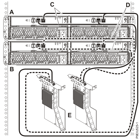
-
Complete a mode 2 connection of one enclosure (A) by using X12 cables
(B) to two FC EJ0L SAS adapter pairs or two FC EJ14 SAS adapter pairs
(C and D) with AA cables (E), as shown in Figure 11. Then, continue with Connecting cables, power cords, and installing covers.
Notes:
- Each adapter in the SAS adapter pair 1 (C) has access to the other adapter in pair 1 and to drive bays D1 - D12.
- Each adapter in the SAS adapter pair 2 (D) has access to the other adapter in pair 2 and to drive bays D13 - D24.
- For SAS adapter pairs, you must attach the cables to the same port on both adapters.
- Both short legs of the cables must attach to the same side of the enclosure and both long legs of the cable must attach to the other side of the enclosure.
Figure 11. Mode 2 connection of one ESLS by using X12 cables to two FC EJ0L SAS adapter pairs or two FC EJ14 SAS adapter pairs with AA cables 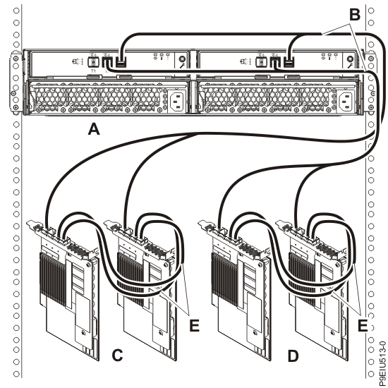
-
Complete a mode 4 connection of one enclosure (A) by using X12 cables
(B) to four independent FC EJ0J or FC EJ0M SAS adapters as shown in Figure 12. Then, continue with Connecting cables, power cords, and installing covers.
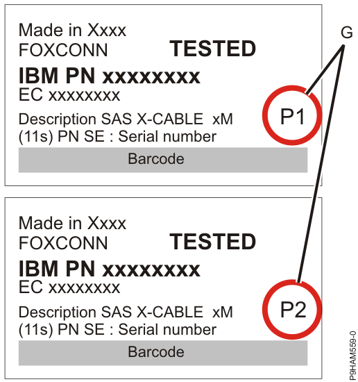
Note: Refer to Figure 13 for label examples of these cable identifiers.
- The cable that plugs into independent SAS adapter 1 (C) contains a label with the P1 identifier (G). This adapter does not have access to any other independent adapter and only has access to drive bays D1 - D6 (D1 - D3 for the ESLL).
- The cable that plugs into independent SAS adapter 2 (D) contains a label with the P2 identifier (G). This adapter does not have access to any other independent adapter and only has access to drive bays D7 - D12 (D4 - D6 for the ESLL).
- The cable that plugs into independent SAS adapter 3 (E) contains a label with the P1 identifier (G). This adapter does not have access to any other independent adapter and only has access to drive bays D13 - D18 (D7 - D9 for the ESLL).
- The cable that plugs into independent SAS adapter 4 (F) contains a label with the P2 identifier (G). This adapter does not have access to any other independent adapter and only has access to drive bays D19 - D24 (D10 - D12 for the ESLL).
Note: Partial mode 4 configurations are supported with less than 4 adapters leaving an adapter end of the X12 cable not connected.Figure 12. Mode 4 connection of one ESLL or ESLS storage enclosure by using X12 cables to four independent FC EJ0J or FC EJ0M SAS adapters 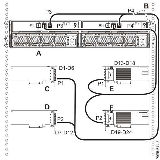
Figure 13. Labels for SAS adapter cables that show P1 and P2 identifiers