Model 8335-GTB water cooling option (Feature code E2RD)
Learn about the water-cooled option that is available for 8335-GTB servers that use 7965-94Y racks, including overview, dimensions, temperature, and environment specifications and requirements.
Overview
Feature code (FC) ER2D is available for order for 8335-GTB servers that use 7965-94Y racks with FC ER22 or ER23 installed. For more information about 7965-94Y racks with FC ER22 or ER23 installed, see Planning for the 7953-94X and 7965-94Y rack.
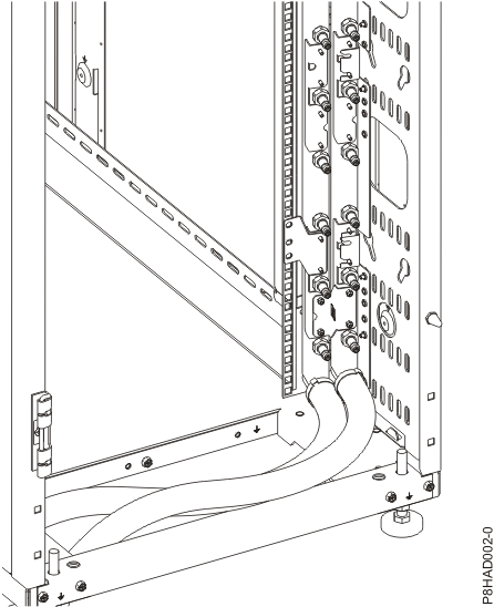
For more information about water cooling requirements, see Water cooling system specification and requirements.
| Configuration | Weight |
|---|---|
| Single server (dry) | 29.5 kg (65 lbs) |
Note: The weight of the water
in the server is negligible. For more information about the weight
of manifold with water, see Model 7965-94Y water cooling manifold (Feature codes ER22 and ER23).
|
|
The rear door heat exchanger can be used with this rack. For more information about rear door heat exchangers, see Model 1164-95X rear door heat exchanger specifications.
Cooling capacity
The manifold cools a portion of the total heat of the system (the heat that is created by the processors and the GPUs). The remaining heat from the system must be cooled by air within the data center. Table 2 contains the approximate amounts of heat that go to water and air. Your server configuration, workload, and server settings varies the amount of heat from the processor and the GPUs that can be cooled by the water and the amount of cooling that is required for other components.
Heat removal to water can vary from 60% to 75% based on air inlet temperature, water inlet temperature, and fan speed. An example is shown below. For a maximum configured system that is running at recommended conditions with about 0.8 gallons per minute (GPM) water flow rate, approximately 68% of the heat is removed by water and 32% of the heat is removed by air.
| Cooling type | Maximum power consumption | Thermal output |
|---|---|---|
| Heat to water | 1300 Watts | 4436 BTU/hr |
| Heat to air | 600 Watts | 2047 BTU/hr |
| 1Preliminary data is subject to change. | ||
Required flow rate versus water temperature curve
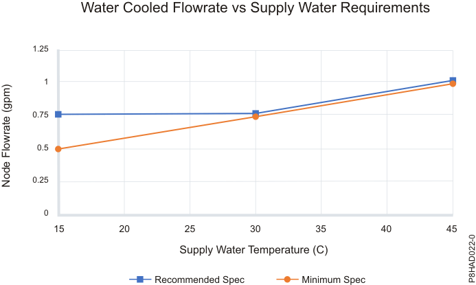
Figure 2 shows the recommended flow rate per node, as a function of the supply water temperature. The IBM® recommended specifications are shown by the upper blue curve. The lower minimum specification curve must only be used if facility infrastructure issues require the hottest return water temperature. The maximum flow rate must not exceed 1.1 GPM.
Water flow rate versus pressure drop
- Supply Eaton ball valve pair
- Supply hose between the Eaton ball valve and the manifold
- Supply manifold
- Eighteen 8335-GTB servers
- Return manifold
- Return hose between the return Eaton ball valve and the return manifold
- Return Eaton ball valve pair
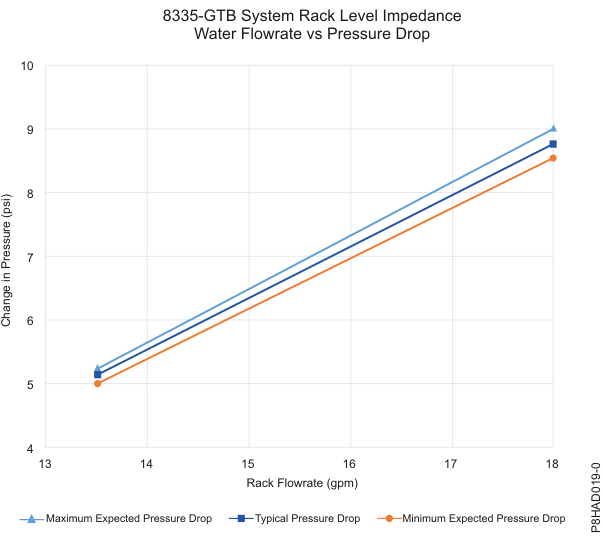
- 0.05 psi per 0.305 m (1 ft.) of hose if the rack-level flow rate is 13.5 GPM.
- 0.09 psi per 0.305 m (1 ft.) of hose if the rack-level flow rate is 18 GPM.
- 1.4 psi (0.05 psi multiplied by 28 ft.) if the rack-level flow rate is 13.5 GPM.
- 2.5 psi (0.09 psi multiplied by 28 ft.) if the rack-level flow rate is 18 GPM.
Temperature rise curve
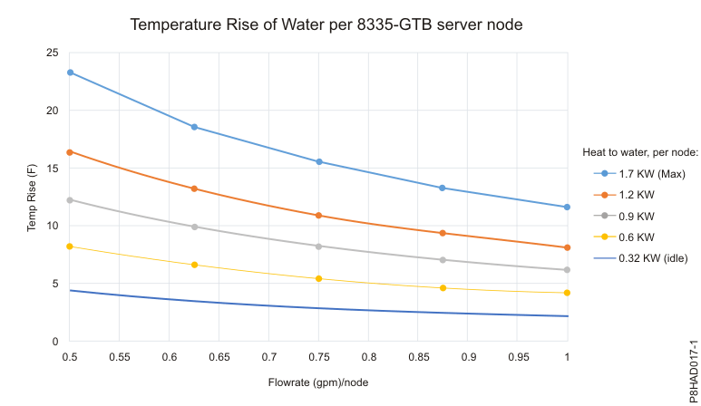
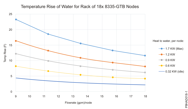
The following graphs show the estimation of the rise in water temperature that is based on the inlet flow rate to the server and the total heat load to the water.
Figure 4 shows this information for a single server. Figure 5 shows this information for a full rack of 18 servers.
The lowest heat load value at 0.32 kW is for an idle condition. The highest heat load value at 1.7 kW is for a maximum workload. All calculations are completed by using a system with four GPUs and two CPUs.
Cooling loop requirements
- A secondary cooling loop, separate from the main site cooling loop, is required for the manifold.
- Cooling distribution units are available from suppliers such as Eaton-Williams.
- The secondary cooling loop must meet the requirements that are outlined in the water chemistry specification.
For more information about water chemistry requirements, see Water cooling system specification and requirements.
Environment requirements
| Environment | Recommended operating | Allowable operating | Nonoperating |
|---|---|---|---|
| ASHRAE class | A3 | ||
| Airflow direction | Front-to-back | ||
| Temperature1 | 18°C - 27°C (64°F - 80°F) | 5°C - 40°C (41°F - 104°F) | 1°C - 60°C (34°F - 140°F) |
| Humidity range | 5.5°C (42°F) dew point (DP) to 60% relative humidity (RH) and 15°C (59°F) dew point | -12.0°C (10.4°F) DP and 8% - 80% RH | 5% - 80% RH |
| Maximum dew point | 24°C (75°F) | 27°C (80°F) | |
| Maximum operating altitude | 3050 m (10000 ft) | ||
| Shipping temperature | -40°C to 60°C (-40°F to 140°F) | ||
| Shipping relative humidity | 5% - 100% | ||
|
|||